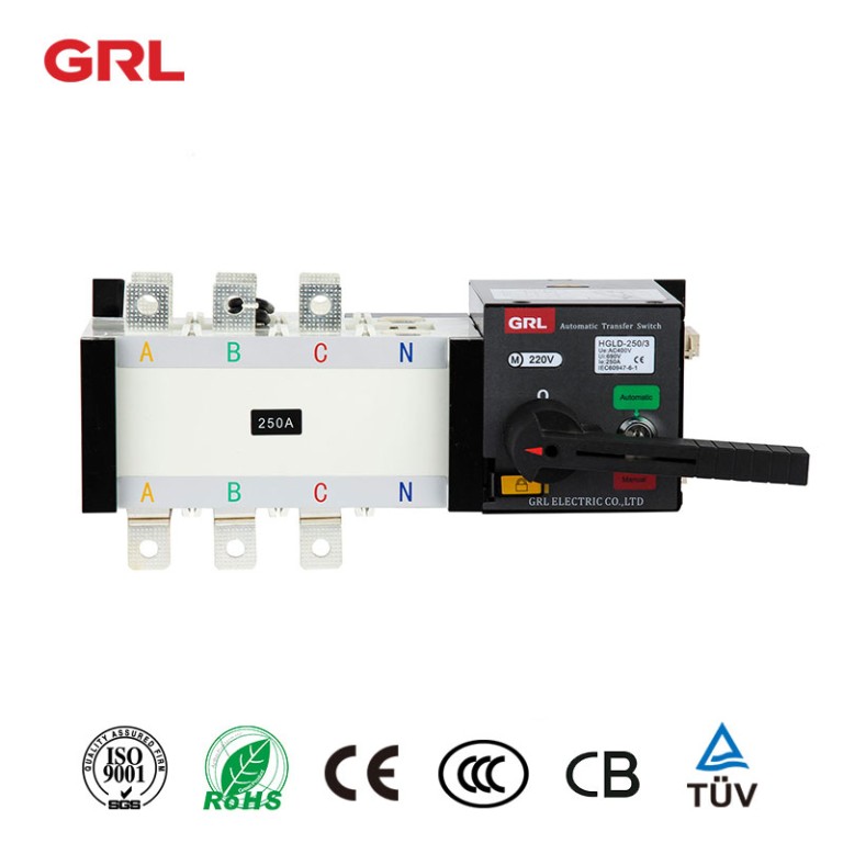
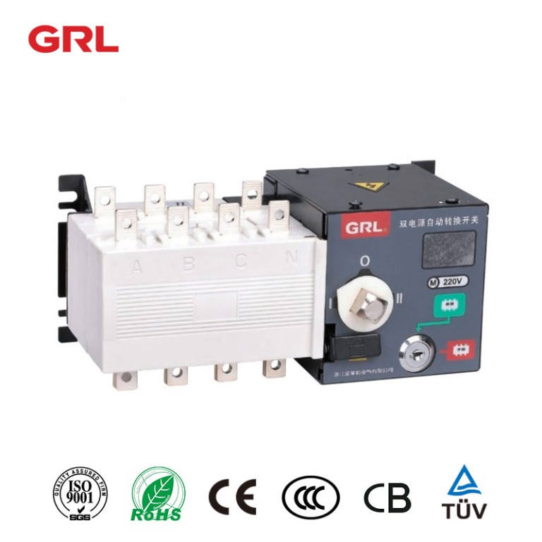
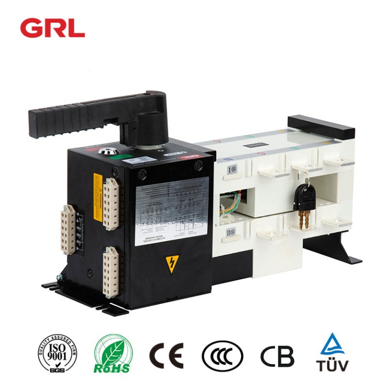
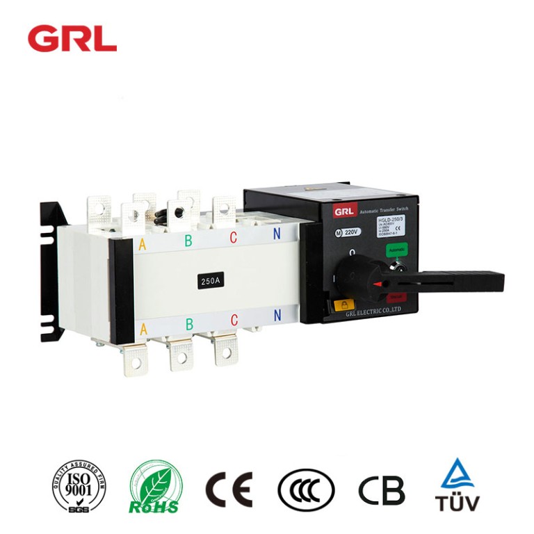
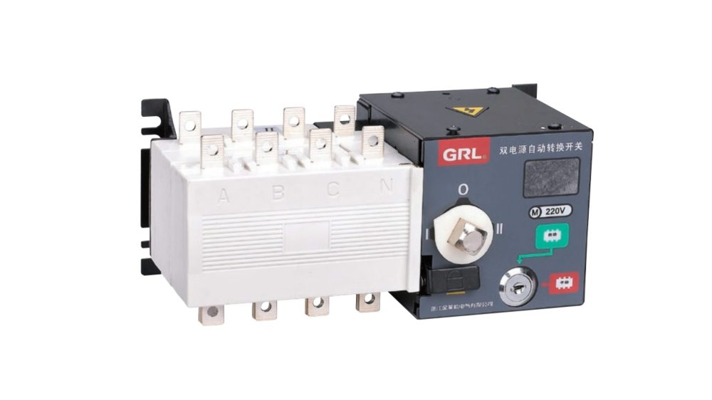
Isolation automatic transfer switches (ATS) are used to physically separate two sources of power, such as a generator and the utility grid. ATSs at the PC level is typically employed in data center and server applications where data centers often have multiple power sources, including the utility grid, generators, and UPSs.
Automatic Transfer Switch Product Overview
The control section of the DNQ8 switch is composed of a metal casing, while the switch itself is made of glass fiber unsaturated polyester resin. This gives the switch superb dielectric performance, as well as dependable protection and safety features.
DNQ8 is also aesthetically pleasing, with a solid structure and compact form factor. It is the ideal choice for a variety of applications.
Application of Automatic Transfer Switch
The DNQ8 series automatic transfer switch is an important device for powering various systems and equipment. It is mainly used for distributing AC power at 50Hz, with a rated voltage of 400V and a DC rated voltage of 220V. It also has a rated current of 16 to 3200A.
Additionally, the DNQ8 series automatic transfer switch can be used for the switching system of one main and one standby power supply, or mutual standby power supply in a motor network. Furthermore, it can be used for infrequent isolation from breaking circuits and lines. In sum, the DNQ8 series automatic transfer switch is versatile and indispensable
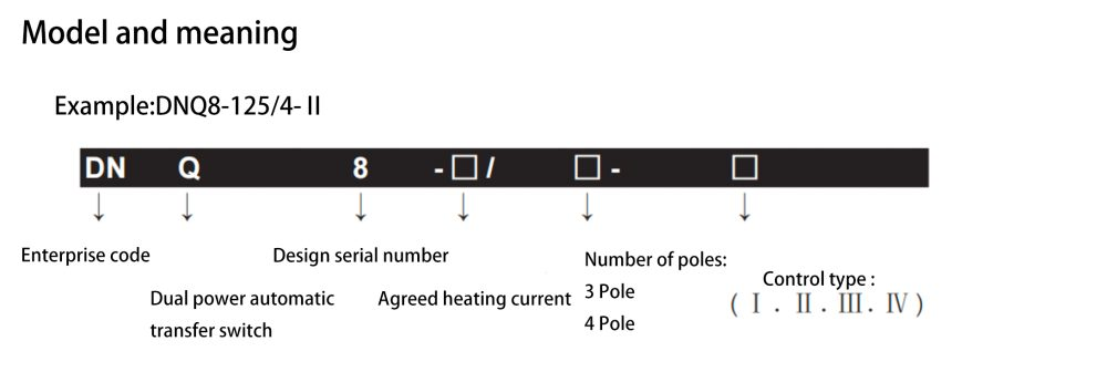
Example of Model Selection
The automatic transfer switch, with the agreed heating current of 125 amps, the AC rated voltage of 400 volts, the rated current of 50 amps, 4 poles (3 poles + interruptible neutral pole), is suitable for the automatic switching and automatic recovery of the power supply system of municipal power and oil engine.
Meet The Standard
DNQ8 series automatic transfer switch symbols the following standards:
International Standard
- IEC60947-1 low voltage switchgear and controlgear part I General
- IEC60947-3 low voltage switchgear and control equipment, switches, isolators, disconnectors and fuse combinations
- IEC60947-6 low voltage switchgear and control equipment multi function switch automatic transfer switching apparatus
National Standard
- GB/T14048.1 general rules for low voltage switchgear and controlgear
- GB14048.3 low voltage switchgear and control equipment, low voltage switches, isolators, disconnectors and fuse combinations
- G814048.11 low voltage switchgear and control equipment multifunctional electrical appliances transfer switching appliances
Main Technical Parameters
| Agreed heating current Ith | 16 | 20 | 32 | 40 | 50 | 63 | 80 | 100 | 125 | 160 | 250 | 400 | 630 | 800 | 1000 | 1250 | 1600 | 2000 | 2500 | 3200 | |
| Rated insulation voltage Ui | 500V | 690V | 800V | ||||||||||||||||||
| Rated impulse withstand voltage Uimp | 6kV | 8kV | 12kV | ||||||||||||||||||
| Rated working current Ie | 16 | 20 | 32 | 40 | 50 | 63 | 80 | 100 | 125 | 160 | 250 | 400 | 630 | 800 | 1000 | 1250 | 1600 | 2000 | 2500 | 3200 | |
| Rated short-time withstand current Icw(0.5s) | 5kA | 8kA | 12.5kA | 32kA | |||||||||||||||||
| Use category | AC33B | AC33iB | |||||||||||||||||||
| Rated working voltage Ue | AC400V | ||||||||||||||||||||
| Control motor voltage | AC220V | ||||||||||||||||||||
| Conversion timeⅠ-Ⅱ or Ⅱ-Ⅰ | 0.7S | 1.8S | |||||||||||||||||||
| Mechanical life times | 8000 | 6000 | 3000 | 2000 | |||||||||||||||||
| Electrical life times | 3000 | 2500 | 1500 | 1000 | |||||||||||||||||
| Weight 4 pole kilograms | 3.4 | 6.0 | 7.5 | 15.5 | 17 | 32 | 36 | 37 | 40 | 60 | 62 | 68 | |||||||||
Performance and Characteristics
The DNQ8 automatic transfer switch is a dual-power dual-row composite contact that uses horizontal pulling mechanisms, micro-motor pre-storage, and micro-electronic control technology to achieve zero arcing. It has reliable mechanical and electrical interlocking, no element actuator, and an independent load isolation switch.
The DNQ8 uses zero-crossing technology to meet the needs of fire linkage. It has obvious switch position indication, padlock, and other functions to safely and reliably isolate power and load.
There are four operation functions: emergency manual operation, electric remote control operation, emergency disconnection operation in automatic.
Operating Environment
- The maximum altitude shall not exceed 2000 meters.
- The temperature shall not exceed 40 ℃, and shall not be lower than -5 ℃. The relative humidity shall not exceed 95%.
- No explosive medium environment.
- No rain or snow invasion environment.
Note:
The ambient air temperature outside of the recommended +40℃ to -5℃ to -45℃ range may impact the performance of this product. Please consult the manufacturer if you expect this product to be used in these conditions.
Current Parameters
The switch has three poles and four grade (three poles + on-off neutral pole) products.
There are 27 current levels, including 16a, 20a, 25A, 32a, 40a, 50a, 63A, 80A, 100A, 125A, 160A, 200A, 225A, 250A, 315A, 350A, 400A, 450A, 500A, 630A, 800A, 1000A, 1250A, 1600A, 2000a, 2500A, 3200A, etc.
Introduction to Model Selection
Type I (basic type)
Fully automatic, mains power – mains power, external switch closing signal indicator
Type II (power generation and fire protection)
Fully automatic, mains power, mains power generation, can be forcibly switched to common, standby, double split (fire fighting), with generator signal output.
Type III (phase failure protection type)
Fully automatic, mains power mains power, mains power generation, can forcibly switch between common, standby and double split (fire fighting). When the common end detects a lack of phase, it can start the generator signal output or commonly switch to the standby power supply.
Type IV (undervoltage protection type)
Fully automatic, mains power, mains power generation, which can be forcibly switched between common, standby and double split. DC24V fire-fighting function, with generator signal output. In case of undervoltage or phase loss of common terminal phase line, the generator signal output can be started or the common power supply can be switched to standby power supply.
Introduction of Split External Intelligent Controller
Over voltage, under voltage and lack of equality fault detection of common and standby power supplies.
The switching delay of common and standby is adjustable.
Manually select the common and standby power supply and disconnect the two power supplies.
The action status indicator is displayed.
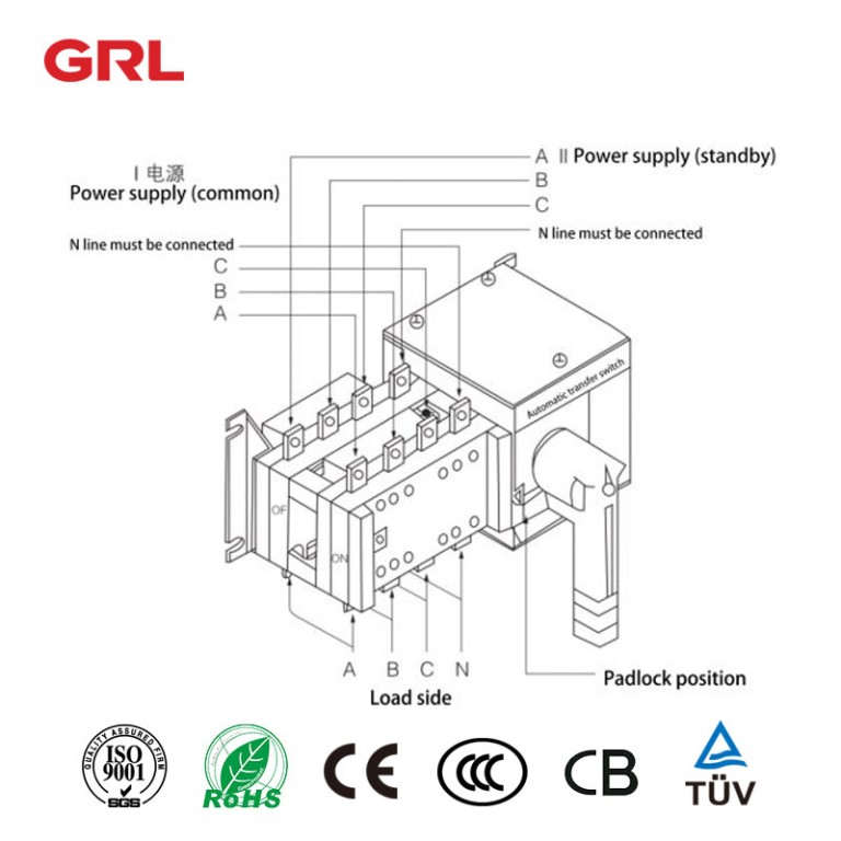
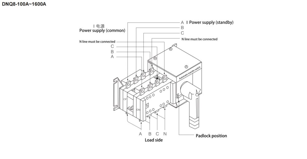
Wiring diagram
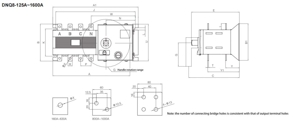
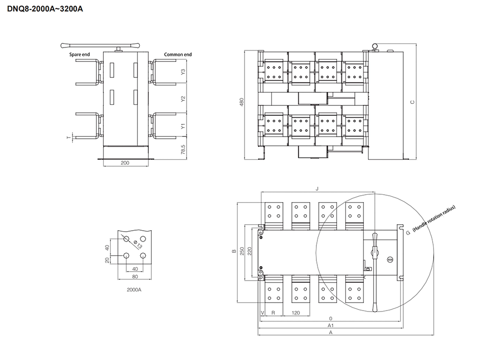
Automatic transfer switch Outline and installation dimension (mm)
| In | A | A1 | B | B1 | C | E | G | J | K | L | N | P | R | S | T | U | W | X | Y | Y1 |
| 125A/3 | 376 | 283.5 | 135 | 134 | 261 | 208 | 166 | 262.5 | 78/108 | 7 | 87 | 36 | 20 | 25 | 3.5 | 134 | 155 | 9 | 56 | 141 |
| 125A/4 | 406 | 316 | 135 | 134 | 261 | 208 | 166 | 295 | 78/108 | 7 | 87 | 36 | 20 | 25 | 3.5 | 134 | 155 | 9 | 56 | 141 |
| 160A/3 | 376 | 283.5 | 135 | 134 | 261 | 208 | 166 | 262.5 | 78/108 | 7 | 87 | 36 | 20 | 25 | 3.5 | 134 | 155 | 9 | 56 | 141 |
| 160A/4 | 406 | 316 | 135 | 134 | 261 | 208 | 166 | 295 | 78/108 | 7 | 87 | 36 | 20 | 25 | 3.5 | 134 | 155 | 9 | 56 | 141 |
| 200A/3 | 416 | 323.5 | 170 | 134 | 261 | 208 | 166 | 302.5 | 78/108 | 7 | 87 | 50 | 25 | 30 | 3.5 | 134 | 164 | 11 | 60 | 145 |
| 200A/4 | 466 | 373.5 | 170 | 134 | 261 | 208 | 166 | 353 | 78/108 | 7 | 87 | 50 | 25 | 30 | 3.5 | 134 | 164 | 11 | 60 | 145 |
| 250A/3 | 416 | 323.5 | 170 | 134 | 261 | 208 | 166 | 302.5 | 78/108 | 7 | 87 | 50 | 25 | 30 | 3.5 | 134 | 164 | 11 | 60 | 145 |
| 250A/4 | 466 | 373.5 | 170 | 134 | 261 | 208 | 166 | 353 | 78/108 | 7 | 87 | 50 | 25 | 30 | 3.5 | 134 | 164 | 11 | 60 | 145 |
| 400A/3 | 455 | 378.5 | 240 | 208 | 333 | 270 | 166 | 358.5 | 176 | 11 | 103.5 | 65 | 30 | 40 | 5 | 208 | 197 | 12 | 83 | 193 |
| 400A/4 | 515 | 438.5 | 240 | 208 | 333 | 270 | 166 | 418.5 | 176 | 11 | 103.5 | 65 | 30 | 40 | 5 | 208 | 197 | 12 | 83 | 193 |
| 630A/3 | 455 | 378.5 | 260 | 208 | 333 | 270 | 160 | 358.5 | 176 | 11 | 103.5 | 65 | 40 | 50 | 6 | 208 | 197 | 12 | 83 | 194 |
| 630A/4 | 515 | 438.5 | 260 | 208 | 333 | 270 | 160 | 418.5 | 176 | 11 | 103.5 | 65 | 40 | 50 | 6 | 208 | 197 | 12 | 84 | 194 |
| 800A/3 | 871.5 | 524 | 340 | 250 | 387 | 319.5 | 448 | 499 | 212 | 11 | 88 | 120 | 60 | 69 | 8 | 250 | 198.5 | 12.5 | 84 | 252 |
| 800A/4 | 975.5 | 637.5 | 340 | 250 | 387 | 319.5 | 448 | 612.5 | 212 | 13 | 88 | 120 | 60 | 69 | 8 | 250 | 207 | 12.5 | 107 | 252 |
| 1000A/3 | 871.5 | 524 | 340 | 250 | 387 | 319.5 | 448 | 499 | 212 | 13 | 88 | 120 | 60 | 69 | 8 | 250 | 198.5 | 12.5 | 107 | 252 |
| 1000A/4 | 975.5 | 637.5 | 340 | 250 | 387 | 319.5 | 448 | 612.5 | 212 | 13 | 88 | 120 | 60 | 69 | 8 | 250 | 207 | 12.5 | 107 | 252 |
| 1250A/3 | 871.5 | 524 | 369 | 250 | 387 | 319.5 | 448 | 499 | 212 | 13 | 88 | 120 | 80 | 69 | 8 | 250 | 198.5 | 13 | 107 | 252 |
| 1250A/4 | 975.5 | 637.5 | 369 | 250 | 387 | 319.5 | 448 | 612.5 | 212 | 13 | 88 | 120 | 80 | 69 | 8 | 250 | 207 | 13 | 107 | 252 |
| 1600A/3 | 871.5 | 524 | 376 | 250 | 387 | 319.5 | 448 | 499 | 212 | 13 | 88 | 120 | 80 | 69 | 10 | 250 | 198.5 | 13 | 109 | 253.5 |
| 1600A/4 | 975.5 | 637.5 | 376 | 250 | 387 | 319.5 | 448 | 612.5 | 212 | 13 | 88 | 120 | 80 | 69 | 10 | 250 | 207 | 13 | 109 | 253.5 |
| Specifications | A | A1 | B | C | G | J | O | R | S | T | V | Y1 | Y2 | Y3 |
| 2000A/3 | 785 | 535 | 423 | 560 | 360 | 408 | 490 | 80 | 81 | 10 | 30 | 113 | 121 | 113 |
| 2000A/4 | 1080 | 650 | 423 | 560 | 540 | 523 | 605 | 80 | 81 | 10 | 30 | 113 | 121 | 113 |
| 2500A/3 | 785 | 535 | 433 | 560 | 360 | 408 | 490 | 80 | 81 | 15 | 30 | 118 | 116 | 118 |
| 2500A/4 | 1080 | 650 | 433 | 560 | 540 | 523 | 605 | 80 | 81 | 15 | 30 | 118 | 116 | 118 |
| 3150A/3 | 785 | 535 | 443 | 560 | 360 | 408 | 490 | 80 | 81 | 20 | 30 | 113 | 111 | 123 |
| 3150A/4 | 1080 | 650 | 443 | 560 | 540 | 523 | 605 | 80 | 81 | 20 | 30 | 113 | 111 | 123 |
Automatic transfer switch Wiring diagram
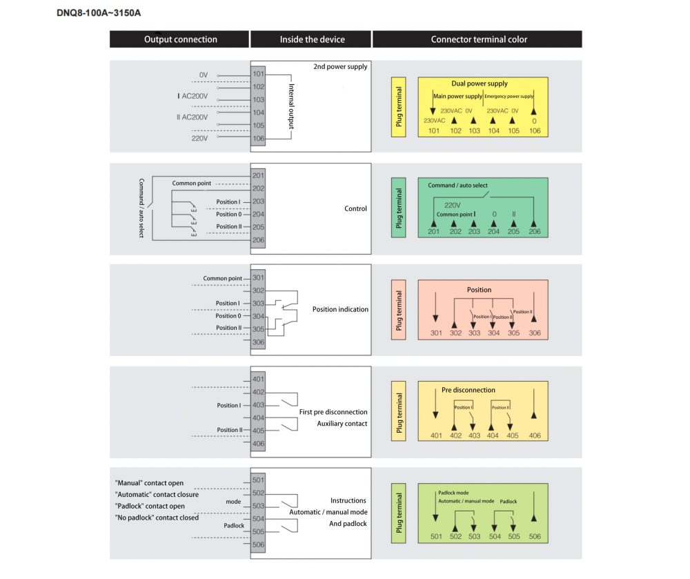
Automatic transfer switch Patch terminal diagram
What is an Automatic Transfer Switch Equipment(ATSE)?
Understanding ATSE
Automatic Transfer Switch Equipment(ATSE) is a crucial component in power systems designed to ensure the continuous and reliable supply of electricity.
Automatic Transfer Switch Equipment(ATSE) seamlessly switches the power source from the primary supply to a backup supply in the event of a power failure or abnormal voltage conditions.
With a switching speed measured in milliseconds, Automatic Transfer Switch Equipment(ATSE) is essential for environments that cannot tolerate power interruptions, such as hospitals, data centers, communication stations, and industrial production lines.

How Automatic Transfer Switch Equipment(ATSE) Works
ATSE constantly monitors the status of the primary power source, checking parameters like voltage and frequency.
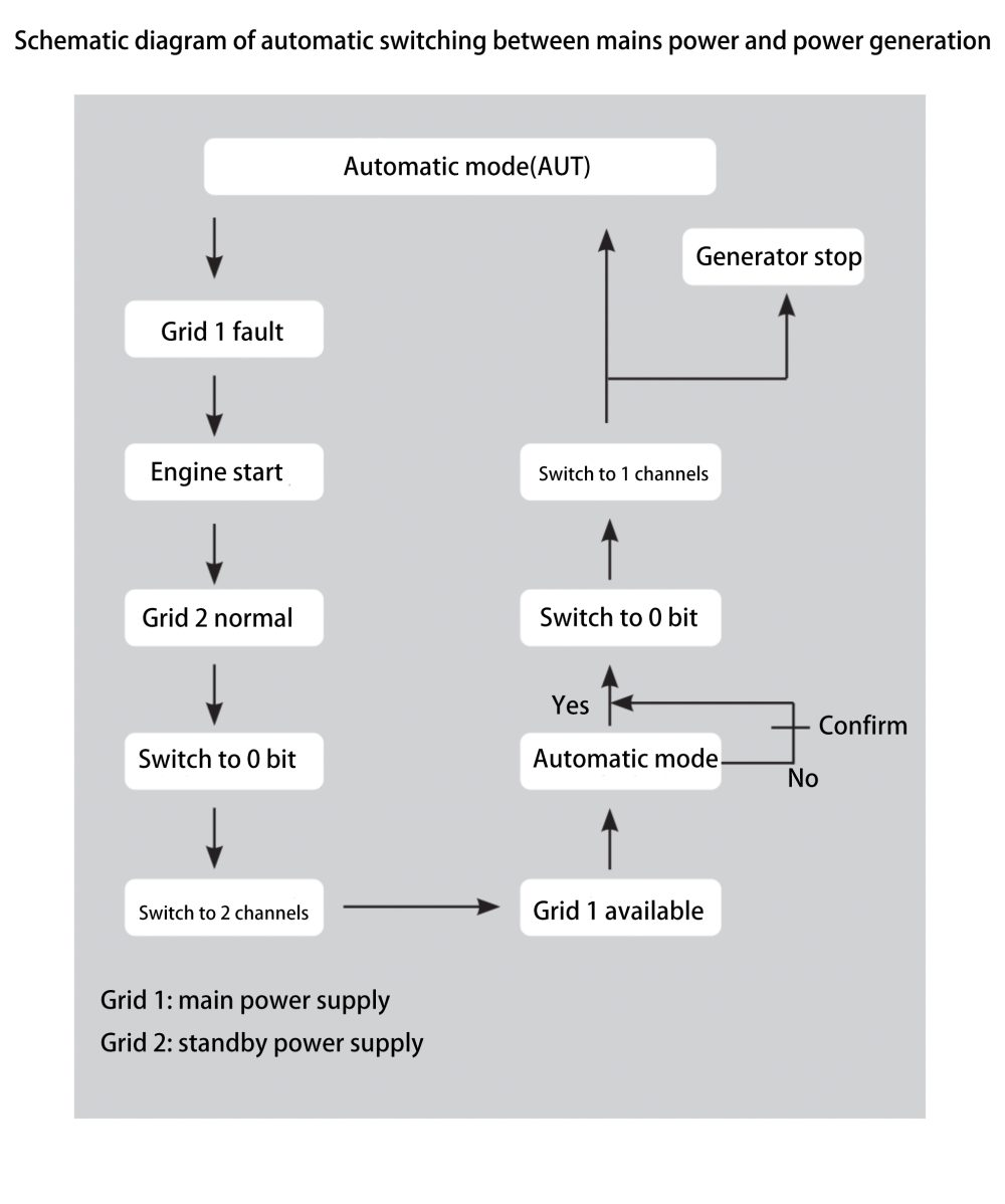
When it detects an issue, such as a power outage, undervoltage, or overvoltage, it swiftly executes a pre-set switching strategy, transferring the load to a backup power source. This backup source could be a generator, an Uninterruptible Power Supply (UPS), or another independent power source.
Once the primary power is restored and stabilized, ATSE can switch back to the main power source according to predefined delay settings.
Applications of Automatic Transfer Switch Equipment(ATSE)
A dual power supply system is designed with an automatic transfer switch that rapidly switches to a backup power source when the primary supply fails or experiences a blackout. This transfer occurs within milliseconds to a few seconds, ensuring that equipment and systems remain operational during power interruptions.
The primary goal of a dual power supply system is to enhance the reliability and stability of power for critical equipment and systems.
It is ideal for environments that demand high power stability and continuity, such as data centers, communication stations, medical devices, and financial transaction systems.
Healthcare Facilities: In hospitals, power outages can have life-threatening consequences. ATSE ensures immediate switching to backup power in critical areas like operating rooms and intensive care units, providing uninterrupted power supply to essential medical equipment.

Data Centers: Data centers require 24/7 power to keep servers, storage devices, and network infrastructure running. ATSE quickly switches to backup generators or UPS systems in the event of a primary power failure, preventing data loss and service interruptions.
Communication Stations: Communication infrastructure relies on constant power to maintain network operations. ATSE ensures a seamless transition to backup power during grid failures, ensuring the stability of communication services.
Industrial Manufacturing: Continuous production processes are crucial in manufacturing. ATSE prevents costly downtime and production losses by providing continuous power to equipment, ensuring smooth industrial operations.
Public Infrastructure: In public places like airports, subway stations, and shopping malls, ATSE ensures that lighting, security systems, and other critical equipment remain operational during power outages, maintaining public safety.
What role does a dual power supply system play in data centers?
The main goal of using a dual power supply system in data centers is to boost system reliability and stability. With two separate power paths, the system can automatically switch to a backup power source if the primary one fails or requires maintenance.
This setup ensures that critical equipment and servers in the data center continue to operate, minimizing the risk of business disruptions and data loss due to power issues.
Dual power supply systems also support dynamic load balancing in data center designs, preventing any single power source from being overloaded and enhancing overall server performance and stability.

Moreover, a dual power supply system safeguards server hardware by seamlessly switching to the backup power source when an issue arises with the main supply, preventing potential damage to hardware from power failures.
These systems are designed with cost-efficiency and compatibility in mind, allowing for quick power restoration during unexpected outages, thereby protecting business continuity and avoiding unnecessary losses.
Highly compatible dual power supply systems can integrate smoothly with existing power infrastructures, reducing the need for extensive modifications or upgrades while improving overall system stability and reliability.
In short, the role of a dual power supply system in data centers is to provide redundant power, facilitate automatic switching and load balancing, protect server hardware, and enhance system reliability and stability, ensuring continuous business operations and data security.
Benefits of Using Automatic Transfer Switch Equipment(ATSE)
Enhanced Power Reliability: ATSE provides immediate switching to backup power when the primary source fails, ensuring uninterrupted power supply. This is vital for critical environments that cannot afford downtime.
Automated Operation: ATSE performs fully automated power switching without the need for human intervention, reducing complexity and labor costs. Automation also minimizes the risk of human error, improving overall system reliability.
Equipment Protection: By managing power transitions smoothly, ATSE prevents voltage fluctuations that can damage equipment, extending its lifespan and reducing maintenance costs.
Safety: In fields like healthcare, communication, and industrial production, power interruptions can lead to severe safety hazards. ATSE ensures rapid switching, maintaining the safe operation of essential systems and protecting both people and assets.
Economic Benefits: By minimizing power outage-induced production and service interruptions, ATSE helps businesses reduce financial losses and enhance operational efficiency.
Why Choose GRL’s Automatic Transfer Switch Equipment(ATSE) DNQ8 Solutions?
At GRL, we offer high-performance ATSE solutions tailored to meet the demands of various industries.
Our ATSE products are designed for seamless power switching, ensuring reliability and safety in critical applications. With GRL’s ATSE, you gain:
- Unmatched Reliability: Our ATSE systems are engineered for rapid response, ensuring your operations remain uninterrupted even during power failures.
- Advanced Technology: GRL’s ATSEsolutions incorporate cutting-edge technology for real-time monitoring and swift switching, providing peace of mind and operational security.
- Custom Solutions: We understand that different industries have unique power needs. GRL provides customizable ATSE solutions to fit your specific requirements.
- Cost-Efficiency: By choosing GRL’s ATSE, you not only invest in power continuity but also in reducing downtime and protecting your equipment, translating into long-term cost savings.
ATSE is an indispensable part of any power system, ensuring continuous power supply in a wide range of environments. From healthcare and data centers to industrial manufacturing and public infrastructure, ATSE plays a crucial role in maintaining operational stability and safety.
GRL is committed to delivering top-tier ATSE solutions, combining reliability, advanced technology, and customization to meet the unique demands of our clients. Choose GRL’s ATSE solutions for a reliable, safe, and uninterrupted power experience.
Of course, we also have a manual transfer switch

leave your question
GRL Electric Co., Ltd. is one of the leading companies in the Middle And High End market of low-voltage electric in China

